
Wiring 8-pin SwitchCraft for xLite v3
This post explains the wiring and pin out order we chose to use when we leverage the 8 pin SwitchCraft port for delivering the charge circuit and CAN bus from the controller box to the battery box via a custom harness.
Important Notes
The xLite v3 has an integrated BLE (Bluetooth) module that allows you to connect directly from VESC Tool. This means that the 5v, Gnd, CAN Hi, and CAN Lo are optional. Even without the CAN wiring, the xLite will still operate during charging and allow you to connect. If you would like your BMS to power on when your VESC powers on so that you can connect to and read your xLite stats/data without being connected to the charger then you must wire up the CAN connections.
If you do not want to wire up the CAN bus connections, the 8 pin switchcraft may not be the best option unless you would like to utilize the unused pins for something such as lighting.
Soldering to the back of the 8 pin SwitchCraft port is very tedius. I recommend starting with the center pin first as it is harder to reach once you have soldered other wired around it.
Older Ennoid xLite versions
Older versions of the Ennoid xLite did not have an isolated CAN bus, so you could not deliver power to the BMS and CAN bus at the same time or else it might cause issues. For this reason we cannot recommend this wiring method for anything but V3 or later.
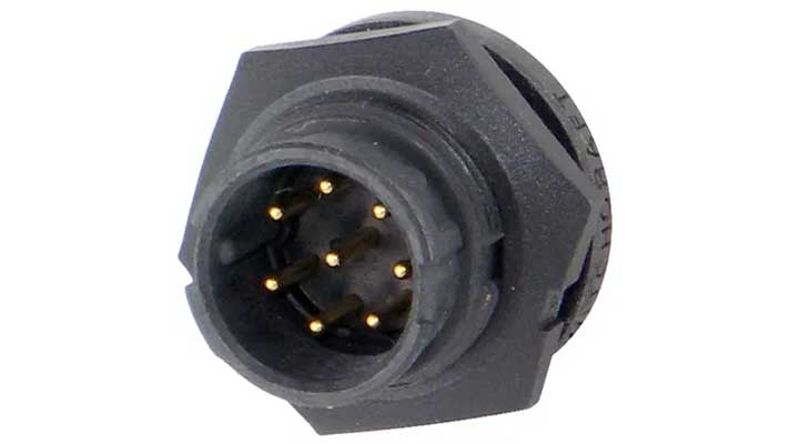
Diagram (v3+ Only)
The pinout diagram provided is looking at the exposed male pin side of the connector.